Wind Turbine


Solid Mechanics and Beam Theory
The principles of solid mechanics and beam design theory factored heavily in the design of our beam. The design of the tower to resist significant deflection simply boiled down to a cantilevered beam of non-uniform cross-sectional area with a concentrated load applied at the end, whose internal shear and bending moments could be predicted and analyzed using formulas whose derivations are rooted in Newtonian mechanics. Many critical elements of the tower were decided with the basic cantilevered beam structure in mind.
Tower Design
The starting point for the tower design were the several sketches that each group member contributed. These concepts each have their merits, yet through careful deliberation, the team has arrived on one design. The tower of a wind turbine has to do more than just to support the generator. Throughout a wind turbine’s deployment, the tower has to withstand forces from wind in multiple directions. The tower also needs to be manufacturable using affordable and accessible processes. The tower also needs to be easy to assemble without the use of specialized hardware. By project guidelines, the material used in constructing the tower cannot exceed a volume of 18 cubic inches, and the tower must allow for a generator shaft height of 16 inches with a tolerance of 1/16 inch. Our design takes all of these requirements into consideration.
The initial concept for the tower used a cross section reminiscent of a crosshair. Four thin long spokes made the design axially symmetric, a requirement for adequate completion of this project. We soon realized that this was not feasible since the tower would encroach on the sweep area for the blades of the turbine. Therefore, a taper was added to the tower, where the base has larger physical dimensions than the top plane. An added benefit of this design is that the roughly triangular feature stands up better to lateral loads than a straight feature as some of the force is redirected vertically. The symmetric layout would mean that the tower would react similarly to forces from the two principal directions.
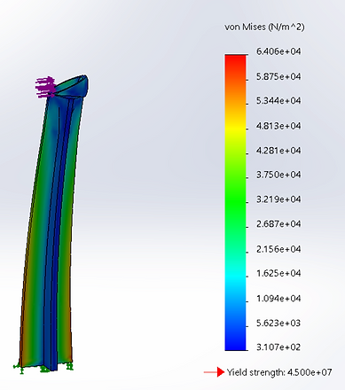
Finite Element Analysis
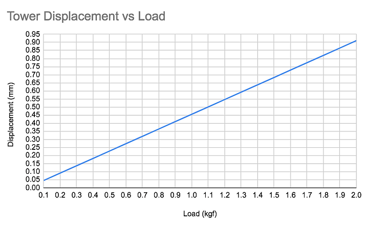
Finite element analysis was performed on a sub-assembly which included only the tower and the motor mount. The turbine was excluded to create a simulation most closely resembling the stiffness testing method of the manufactured towers that was originally planned for the project. We inputted a slightly modified version of the default Solidworks ABS material to account for the anisotropic properties of the material, and to ensure that a reliable factor of safety plot could be created and analyzed. The bottom face of the tower was chosen as the fixed geometry. In addition, the inner face of the motor mount was chosen as the surface which force would be applied to. The simulation was run 20 times, each time with a different load force. This force was chosen from 100g to 2000g in increments of 100g. Following each simulation, the maximum displacement of the tower due to the given load force was recorded and all 20 data points were plotted in order to visualize the stiffness of the tower.
